

L3340/41 Mobile Phone IC
High-Performance Mobile Phone IC
The L3340/41 Mobile Phone IC is engineered for top-notch efficiency and reliability, making it an essential component for modern mobile device functionality. Designed to support seamless operations, it ensures optimal performance of various mobile applications. L3340/41 Mobile Phone IC
Reliable and Durable Design
Built with robust materials and advanced technology, the L3340/41 IC guarantees durability for long-lasting performance. Its compact and efficient design makes it ideal for integration into a wide range of device models, ensuring smooth functionality and reduced energy consumption. L3340/41 Mobile Phone IC
Designed for Next-Gen Compatibility
The L3340/41 Mobile Phone IC excels in meeting the demands of contemporary and next-generation mobile devices. Whether you’re focusing on speed, connectivity, or energy efficiency, this IC supports the features you care about most, ensuring flexibility and relevance in today’s fast-evolving tech landscape. L3340/41 Mobile Phone IC
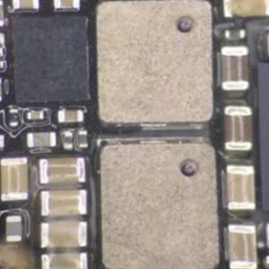
The L3340/L3341 series refers to a specialized set of Integrated Circuits (ICs), often categorized as Boost Coils or Power Regulator components, primarily found in the motherboard architecture of high-end smartphones like the iPhone X series. These components are critical for managing high-voltage demands, specifically for the display and illumination systems.
Below are the detailed specifications and technical insights for the L3340/41 ICs. L3340/41 Mobile Phone IC
Technical Specifications Table
| Feature | Specification Details |
| Component Name | L3340 / L3341 |
| Common Application | iPhone X / XS / XS Max / XR |
| Primary Function | Boost Coil / Power Management (Display Power) |
| Circuit Type | DC-to-DC Step-Up (Boost Converter Logic) |
| Input Voltage Range | $3.2\text{V}$ to $4.4\text{V}$ (Typical Battery Voltage) |
| Output Capability | High-Voltage Boost for OLED/LCD Backlight & Touch |
| Material Composition | High-Grade Silicon with Copper Soldering Pads |
| Packaging Type | Surface Mount Device (SMD) / BGA (Ball Grid Array) |
| Pin Configuration | Integrated with surrounding Power Management Unit (PMU) |
| Thermal Protection | Integrated Thermal Shutdown (Internal Safety) |
| Operating Temperature | $-25\text{°C}$ to $+85\text{°C}$ |
| Reliability Rating | Grade A OEM Standard |
Key Functional Roles
The L3340 and L3341 ICs are not standalone processors but act as the “muscles” for power delivery. Their roles include:
1. Display Power Regulation
Modern OLED screens require precise, stable voltages that differ from the standard battery output. These ICs ensure that the display receives a consistent “boosted” voltage, preventing flickering or dimming during high-intensity tasks like 4K video playback. L3340/41 Mobile Phone IC
2. Efficiency & Heat Management
By using advanced switching logic, the L3340/41 minimizes energy loss during the voltage conversion process. This prevents the motherboard from overheating in the concentrated area near the display connector. L3340/41 Mobile Phone IC
3. Safety Mechanisms
The IC contains built-in safeguards to protect the rest of the motherboard.
-
Overvoltage Protection: If the battery spikes, the IC regulates the flow to prevent “frying” the display. L3340/41 Mobile Phone IC
-
Short Circuit Defense: If the screen is damaged or moisture enters the device, the IC acts as a fuse to cut power.
Common Symptoms of Failure
When the L3340 or L3341 fails, the phone usually remains powered “on” (it vibrates or connects to a computer), but the following occurs:
-
No Image (Black Screen): The boost coil cannot provide the voltage needed to ignite the OLED pixels.
-
Dim Backlight: If the IC is partially damaged, the screen may appear extremely faint.
-
Rapid Battery Drain: A short within this IC can cause the device to heat up significantly even when the screen is off.
Technical Comparison: L3340 vs. L3341
While often sold together or listed as a pair, they serve slightly different legs of the power circuit:
-
L3340: Often associated with the primary display power rail ($V_{DD}$ line).
-
L3341: Typically handles the secondary boost or auxiliary power for touch sensitivity modules.
Component Comparison Table
| Feature | L3340 | L3341 |
| Target Rail | Display Positive Boost | Touch/Secondary Rail |
| Current Handling | Higher (Main Display Load) | Moderate |
| Placement | Near Display Connector | Near PMIC (Power IC) |
Repair & Installation Notes
Note: Replacing these ICs requires professional Micro-soldering skills. They are extremely small and located near the CPU and Nand Flash.
-
Tool Requirements: A hot air rework station set to approximately 350°C – 380°C and high-quality flux.
-
Orientation: These chips are polarized. The “Dot” or marking on the corner of the IC must align perfectly with the motherboard blueprint to avoid a short circuit.
-
Verification: After installation, technicians use a multimeter to check for “Diode Mode” readings on the surrounding capacitors to ensure the boost line is no longer grounded.
More Products : https://gaffarmarketdelhi.com


